Install Gas Fireplace Remote Control Step-By-Step Guide
Master the step-by-step process to add convenient remote operation to your gas fireplace safely and effectively at home.

Install Gas Fireplace Remote Control
Adding a remote control to your gas fireplace transforms it into a modern, user-friendly feature that boosts comfort without requiring constant manual adjustments. These systems typically include a handheld transmitter and a receiver that connects to the fireplace’s gas valve, enabling wireless operation from anywhere in the room. This guide provides a complete roadmap for selecting, installing, and maintaining such a system, drawing from established installation practices to ensure reliability and safety.
Why Upgrade to a Remote-Controlled Fireplace
Remote controls for gas fireplaces offer precise temperature management, timer functions, and effortless on/off operation, reducing physical effort especially in larger living spaces. They integrate seamlessly with millivolt, electronic ignition, or standing pilot systems, extending battery life and minimizing heat exposure for components. Users report improved energy efficiency as remotes allow quick shutoffs and modulated flame heights, potentially lowering gas consumption during casual use.
Common benefits include:
- Elimination of reaching into hot areas to adjust flames.
- Customizable settings like thermostat mode for consistent room warmth.
- Enhanced safety by keeping operations at a distance from open flames.
- Compatibility with smart home ecosystems in advanced models.
Assessing Compatibility with Your Fireplace
Before purchasing, verify your fireplace model’s ignition type: millivolt (thermoelectric generator-powered), electronic spark, or intermittent pilot. Most remotes support TH/TP and THTH/TP terminals on gas valves, but consult your unit’s manual for specifics. Battery-powered receivers suit vent-free or direct-vent setups, while AC-powered options work for electronic modules requiring 24V transformers.
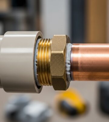
Measure distances: receivers need placement within 20 feet of the valve using 18-gauge wire without splices to avoid signal loss. Check for existing jumper wires on valve terminals, which must be removed during retrofit.
Gathering Essential Tools and Materials
A successful installation demands basic handyman tools and the remote kit, which usually contains a transmitter, receiver, batteries (AA and 9V or 12V), wiring harness, cover plate, and slide switch.
| Tool/Material | Purpose |
|---|---|
| Screwdriver set | Access panels and secure mounts |
| Wire strippers/cutters | Prepare connections cleanly |
| 18-22 AWG wire (if extending) | Reach distant receiver locations |
| Multimeter | Test continuity and voltage |
| Plastic switch box | Wall-mount receiver safely |
Acquire alkaline batteries for longevity, as heat shortens rechargeable types. Safety gear includes gloves and eye protection.
Safety Protocols Before Starting
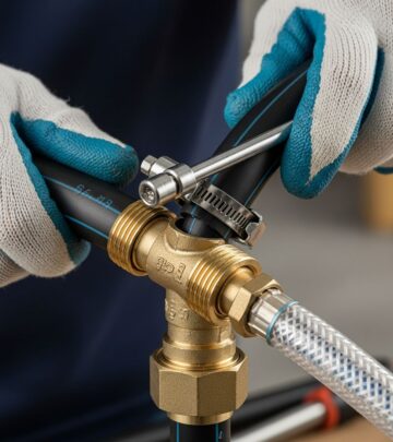
Turn off the gas supply at the valve and main line to prevent leaks. Ensure the pilot is lit where required (standing pilot systems), but extinguish main flames. Disconnect power if electronic ignition is present. Work in a ventilated area, avoiding sparks near gas lines—a qualified gas technician or electrician should handle doubts. Post-installation, test for gas odors and use a leak detector solution on joints.
Step-by-Step Receiver Installation
Locate and Prepare the Receiver Site: Position the receiver on the hearth (away from direct heat over 130°F), under the access panel, or in a wall switch box. Hearth mounts protect from drafts but monitor temperatures; wall boxes shield electronics best.
Install Batteries: Open the receiver compartment, insert four AA batteries matching polarity, and secure the cover. For transmitters, add one 9V or 12V battery. A low-battery indicator often blinks on startup.
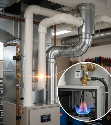
Access the Gas Valve: Remove bottom louvers or panels to expose the valve. Discard any jumper wire bridging TH and TP/TH-TP terminals—this bridges manual to remote mode.
Wiring for Millivolt Systems
Connect one receiver wire to the TH terminal and the other to TP/TH-TP or TH/TP on the valve. No polarity matters in millivolt setups powered by the thermopile. Tug gently to confirm secure fits; use provided harnesses for polarity if labeled.
Wiring for Electronic Ignition
Interrupt the thermostat wire: splice receiver wires in series with TH from the module. Alternatively, connect directly to valve TH and TH/TP, bypassing wall switches. For 24V systems, link to transformer neutrals if specified.
Mount the Receiver: Snap into the cover plate with ‘ON’ upright, aligning the LEARN button. Secure to plastic boxes with provided hardware; avoid metal enclosures that interfere with signals.
Transmitter Pairing and Initial Setup
Set the receiver slide switch to REMOTE. Press the LEARN button (small hole, use a paperclip) until it beeps, indicating pairing mode—within 30 seconds, press the transmitter’s MODE or SET button. The receiver chirps or lights confirm sync; repeat if no response, checking batteries first.
Advanced transmitters feature mode toggles (manual, thermostat, timer) and flame height adjustments via up/down arrows.
Testing the Full System
Manual Test: Slide to ON—pilot ignites (if applicable), then main burner. Slide to OFF—burner extinguishes, pilot stays.
Remote Test: Switch to REMOTE, press transmitter ON. Verify spark/pilot lights, main flame follows. Cycle OFF and test features like timer.
System Checks:
- Spark systems: Electrode sparks, pilot establishes, main opens.
- Millivolt: Thermopile generates ~500mV; measure across terminals.
- No response? Re-pair or inspect wiring.
Troubleshooting Common Problems
Failure to ignite often traces to dead batteries, miswired terminals, or heat-damaged receivers—relocate if over 130°F. Signal interference from fluorescents or metals disrupts pairing; shorten wires or reposition. Weak thermopile in millivolt units (<400mV) needs cleaning or replacement.
| Issue | Solution |
|---|---|
| No remote response | Re-press LEARN, check batteries, ensure REMOTE mode |
| Intermittent flame | Secure wires, test multimeter continuity |
| Overheating receiver | Wall-mount or insulate hearth placement |
| Pilot won’t light | Verify gas supply, clean orifice |
Optimizing Performance and Maintenance
Place the transmitter beyond 4 feet from the fireplace to avoid false readings. Change batteries seasonally; store spares cool. Clean receiver vents yearly and inspect wires for frays. Firmware updates (rare) follow manufacturer apps. Integrate with home automation for voice control in compatible models.
FAQs
Can I install this myself? Yes, for basic DIY skills, but hire a pro for gas/electrical uncertainties.
What if my fireplace lacks TP terminals? Adapter kits or valve-specific remotes exist; check manual.
Is wiring polarity critical? No for DC millivolt; yes for some AC modules—match harness.
How long do batteries last? 6-24 months, depending on use and heat.
Will this void my warranty? Unlikely if following manufacturer instructions.
References
- How To Install A Fireplace Remote – YouTube — YouTube. Accessed 2026. https://www.youtube.com/watch?v=n491t4SDiAM
- FireplaceConceptsLex Remote Instructions — Fireplace Concepts Lex. 2024-05. https://www.fireplaceconceptslex.com/wp-content/uploads/2024/05/FireplaceConceptsLexRemoteInstructions-1.pdf
- How to Install a Skytech Fireplace Remote – SKY-3301 – YouTube — YouTube. Accessed 2026. https://www.youtube.com/watch?v=2g3_hKA_M6E
- SkyTech 1410-A Fireplace Remote Installation Instructions Manual — SkyTech. 2012-11-01. https://www.myfireplaceblower.com/content/SkyTech-1410-A-Fireplace-Remote-Installation-Instructions-Manual.pdf
- How to Install a Skytech Fireplace Remote – SKY-1001-A – YouTube — YouTube. Accessed 2026. https://www.youtube.com/watch?v=55wi_eY9cT0
Similar Articles
Read full bio of Sneha Tete